We remain fully operational. Our teams are working around the clock to ensure your deliveries continue safely.

DOWNLOAD THE APP


Copyright © 2025 Desertcart Holdings Limited
DOWNLOAD THE APP


Navigate Your Projects with Precision! 🧭
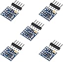
The 5PCS GY-271 QMC5883L Triple Axis Compass Magnetometer Sensor Module is a compact and versatile sensor designed for Arduino and Raspberry Pi enthusiasts. Operating within a supply voltage range of 3.0~5.5VDC, it features a low-noise 16-bit ADC and offers exceptional heading accuracy of less than 2 degrees, making it perfect for a variety of applications including compass sensing and non-contact control.
| ASIN | B08ZHKDJHD |
| Best Sellers Rank | #4,459 in Single Board Computers (Computers & Accessories) |
| Brand Name | AITRIP |
| Color | 5PCS |
| Customer Reviews | 3.1 3.1 out of 5 stars (29) |
| Item Weight | 10 Grams |
| Manufacturer | AITRIP |
| Measurement Type | Gauss |
| Minimum Operating Voltage | 3 Volts (DC) |
| Model | GY-271 |
| Style Name | Compact |
| UPC | 701715465138 |
A**R
Make sure to use the right Arduino Library
At first I was accidentally using the HMC5883L library. That was wrong, this is the QMC5883L. You've probably made this error if the heading hangs at a constant value. I then went and downloaded the QMC5883L library from DFRobot. I found it odd that there was no calibration setting in the example code (you're usually supposed to move the magnetometer around in all orientations to get the x, y, z extrema values, and then input those into the code). It took me a full day to finally realize that the DFRobot library conducts ongoing calibration as you use it. So, if you are going to use this library, the first thing you must do every time you turn on your Arduino is rotate your magnetometer in all different directions. Then you're good to go. Ultimately, I landed on a much more advanced library by mprograms on GitHub (you can find this easily on Google). This library has example code to get your calibration values, and it actually lets you input your calibrations permanently so that you don't need to do it every time you start your Arduino. When you get a good calibration on these things, the data is very clean. The magnetometer seems completed unaffected by any rogue magnetic fields. As far as noise, I'm getting a 6.52 degree standard deviation at a 295 degree heading. That suggests 68% of your values lie within +- 2% of the actual value, and 95% of values within +- 4% (assuming gaussian distribution). Add a little bit of a lowpass to your data and you're golden.
K**P
UNUSABLE.
First off, the I2C address for these items show up as 0x0d. A REAL HCM5883L is at 0x1E. I have code running that works with a BN-880 GPS module which contains a REAL HCM5883L. Same code does NOT work with these boards. EVEN when I change the address used by the Adafruit_HCM5883_U library (to match these boards)... I get NO data. I am able to get the Sensor details. That all reads back fine, but I NEVER get any data from the X,Y or Z registers. If someone wants to explain WHY this is the case, I'd be glad to listen. Otherwise, don't bother trying to use these boards.
G**E
Wrong chip, but they do work
The compasses that arrived didn't work until I found out that mine use the QMC5883P chip, not the L. Luckily Adafruit released an Arduino library for them just a couple of days ago so I can say that they work, just the wrong chip. Judging by other reviews, it looks like others got different chips so you may need to try multiple different libraries to figure out which one you have.
D**R
Fully functional and easy to work with
I have had no problems getting this running. I have not yet tested the accuracy of the magnetic measurement, but it seems valid. My particular chip appeared to follow the datasheet from OSOYOO for the qmc5883l. The sensor address is 0x0D, and the data registers start at register 0x00 and go through 0x05.
A**D
Chipset is HMC5883L
The chips are labeled as QMC5883L; however, the default address is 0x1E instead of 0x8D (the QMC default), and the registers match the mapping for the HMC (output registers 0x03-0x08), not the QMC(output registers 0x00-0x05). If you get these, use an HMC5883L library or remap the registers as needed. Other than that, though, they work fine.
E**K
These boards use reject ICs!
These boards have reject ICs! I spent a lot of hours puzzling why the angles weren't consistent. Finally set up a sketch that reported a single axis. There should be 2 maxima 180 degrees apart, and 2 nulls halfway between. But the nulls were not quite null and definitely not 180 degrees apart! A line of magnetic flux does not bend many degrees across a tiny IC! All X axis readouts were bad. Only two of the 5 boards had Y and Z axis readouts that might be usable.
B**L
Work well with MPU-6050
Work well with custom SlimeVR firmware with MPU6050. Doesn't work with standard SlimeVR firmware currently, must use a forked version.
B**.
Buy 10 get 1 that works
I like these, but they have the highest DOA ratio of ANYTHING I have EVER bought.
Trustpilot
2 days ago
2 weeks ago